A Quick Look at the Hub Pattern
The F´ hub pattern connects components across a boundary while preserving the ordinary typed-port model inside each deployment. The boundary may be an address-space boundary between processes, a platform or processor boundary, or a network or hardware transport. Instead of requiring every component to know about that transport, a pair of hubs serializes calls on one side and deserializes them into typed port calls on the other side.
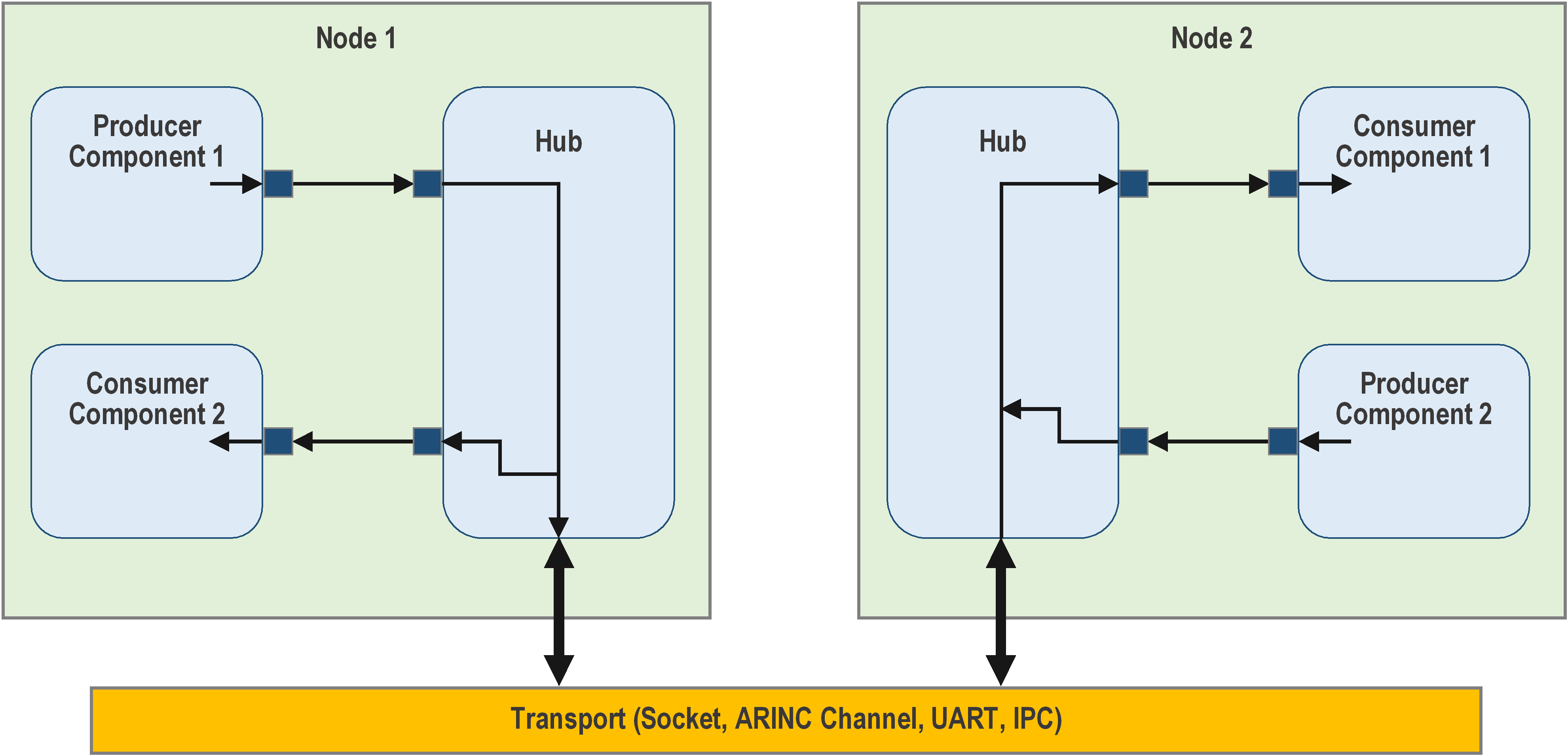
Figure 9. Hub pattern. Each hub instance connects to a remote node. Connections may use sockets, ARINC 653 channels, hardware buses, UARTs, shared memory, or another buffer-based transport.
How it works
The basic arrangement is:
    Component A1 -->--+       +-->-- Component B1
                       |       |
                       Hub A ~~> Hub B
                       |       |
    Component A2 -->--+       +-->-- Component B2
The ~~> is the transport between deployments. In a typical implementation,
each hub is paired with a buffer driver:
On the sending side, the hub allocates a buffer, writes a message-type discriminator, port index, payload size, and serialized payload, and gives the buffer to the driver. The remote driver gives the buffer to its hub, which validates and deserializes it before invoking the corresponding typed output port.
What can cross the hub?
- Serial data: typed port calls whose arguments are serialized by value.
- Events: event ID, time tag, severity, and event arguments.
- Telemetry: channel ID, time tag, and telemetry value.
- Commands: remote command dispatches and command responses through the command splitter and dispatcher interfaces. See the GenericHub SDD for the current command-response limitation.
Do not pass an
Fw::Bufferacross a hub. AnFw::Bufferis essentially a fat pointer: an address into a local address space plus a size. A hub connects components across a system boundary — a separate address space, processor, or transport — where that address is meaningless. In practice it almost never makes sense to send anFw::Bufferthrough a hub; serialize and send the underlying data instead.
Rules for using the pattern
- Configure both hubs with matching array sizes. Hub A's inputs must correspond to hub B's outputs, and hub A's outputs must correspond to hub B's inputs.
- Never pass pointers through a hub. A pointer (including an
Fw::Buffer, which is effectively a fat pointer) is valid only in the address space that owns the pointed-to object; send serialized values instead. - Wire received event and telemetry outputs to the deployment's event manager and telemetry database. A hub transports events and telemetry, but is not itself an event source or telemetry database.
- Use a buffer driver at each end of the transport. The
Drv::ByteStreamBufferAdaptercan pair a byte-stream driver with the buffer-driver interface expected by GenericHub.
Putting it together
A common layout is:
Deployment A                         Deployment B
-------------                        -------------
FSW -> GenericHub -> transport -> GenericHub -> FSW
For a runnable worked example, see
fprime-community/fprime-generic-hub-reference.
Its docs/setup.md
walks through building both deployments and running HubMessageTest for serial,
buffer, event, and telemetry round trips, plus HubCommandTest for
cross-deployment commanding.